RC Time Circuits Explained
Overview
RC circuits, being as simple as they are, are often misunderstood. Formulas such as the time constant (\(\tau=RC\)) or charging equation (\(V_C(t)=V_B(1-e^{\frac{t}{RC}})\)) can be easily overlooked without understanding why the equations exist as they are. This lesson explains how RC circuits work, and builds the formulas from the ground up.
Solving With Constant Current

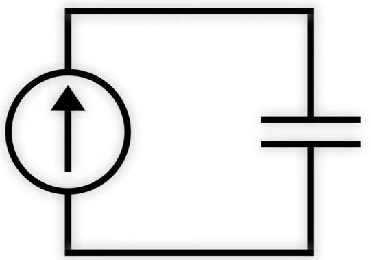
Consider an RC circuit consisting of just a resistor and a constant current source. Such a circuit could be modelled by relating the formula for current to the formula for capacitance as follows:
\(C=\frac{Q}{V}\) *Where \(C\) is capacitance, \(Q\) is charge, & \(V\) is voltage.
By working in differentials (tiny changes), the equation can be rewritten as a function of time:
\(C=\frac{dQ(t)}{dV(t)}\), which can be arranged to: \(dQ(t)=CdV(t)\)
Now the formula for electric current can be introduced:
\(I=\frac{Q}{t}\) which, as a function of time, yields: \(I(t)=\frac{dQ(t)}{dt}\)
Since we initially stated that \(dQ(t)=CdV(t)\), we can substitute into the electric current equation:
\(I(t)=\frac{CdV(t)}{dt}\)
The above equation represents the apparent current through the capacitor as a function of time. In order to solve for the voltage of the capacitor instead of the current through it, we can rearrange the differential equation:
\(I(t)=\frac{CdV(t)}{dt}\)
\(\frac{dV(t)}{dt}=\frac{I(t)}{C}\)
\(\int{\frac{dV(t)}{dt}}dt=\int{\frac{I(t)}{C}}dt\)
\(\int{dV(t)}=\frac{1}{C}\int{I(t)}dt\)
\(V(t)=\frac{1}{C}\int{I(t)}dt\)
In this situation, the integral represents the infinite sum of current passing through the capacitor (which is simply the definition for total charge in time). Here is an example of the equation used in practice:
Suppose a current of 50mA is passing through a 1mF capacitor following the function \(\sin{2t}\). After 1s, what will be the voltage potential across the capacitor?
Solution:
\(V(t)=\frac{1}{C}\int{I(t)}dt\)
\(V(t)=\frac{1}{(1mF)}\int{\sin{2t}}dt\)
\(V(t)=\frac{1}{1mF}(-\frac{\cos{2t}}{2}+C)\)
\(V(t)=\frac{1}{1mF}(-\frac{\cos{2(1)}}{2}+C)\)
\(V(t)\approx{\frac{1}{1mF}(0.20807341827+C)}\) *Assume starting condition to be 0
\(V(t)\approx{\frac{1}{1mF}(0.20807341827)}\)
\(V(t)\approx{0.20807341827}V\)
Note that for equations where the current isn't changing, the function becomes linear and is reduced to: \(V=\frac{It}{C}\)
Modelling the RC Circuit

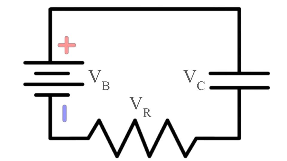
The reason that this approach does not work when a resistor is inserted is because the resistor's voltage drop changes as the capacitor charges. This is because the difference between the capacitor's cathode voltage & the negative supply voltage decreases as the capacitor charges, and thus the current through the resistor does as well (See Ohm's Law). To understand the charging relationship for a capacitor when inserted into a more complex circuit, the circuit can be analyzed according to Kirchoff's Voltage Law (KVL). Since the algebraic sum of all voltages around a closed loop is zero, this equation can be constructed:
\(V_B+(-V_C)+(-V_R)=0\) *Voltages are negative due to their role in the voltage loop
The final formula that should be achieved is a voltage function given in terms of capacitance, resistance, initial voltage, and time. In order to do this, the KVL equation has to be written in those terms:
\(V_B-V_C(t)-I(t)R=0\) *Sub in value for current in terms of charge & time
\(V_B-V_C(t)-(\frac{dQ(t)}{dt})R=0\) *Represent charge in terms of capacitance & voltage. We can do this because the current through the capacitor is equal to the current through the resistor (See KCL)
\(V_B-V_C(t)-(C\frac{dV(t)}{dt})R=0\)
What remains is a Separable Differential Equation, the solution of which returns a function of the capacitor voltage in terms of capacitance value, resistance, & time. In order to find a solution, it must first be arranged into the standard solvable form:
\(RC\frac{dV(t)}{dt}+V_C(t)=V_B\)
Solving the Differential Equation
Usually an equation of this manner can be solved through algebraic manipulation and integration. The issue is that the equation consists of a non-zero right hand term. This indicates that a homogeneous solution and non-homogeneous solution are required. The particular solution in this case would represent the battery voltage, as it is the term located on the right side. In calculus, this is referred to as a "forcing function" as it appears as a constant value in time and is not affected by any other variables. The next step would be to solve the homogeneous part of the equation. In order to do this, we can set the right hand side to 0 and express the formula so that the derrivative appears as a single isolated term in the equation.
\(RC\frac{dV(t)}{dt}+V_C(t)=0\)
\(\frac{dV(t)}{dt}+\frac{V_C(t)}{RC}=0\)
All of the variables affected by the derrivative should be placed on the left side:
\(\frac{dV(t)}{dt}=-\frac{V_C(t)}{RC}\)
\(\frac{1}{V_C(t)}\cdot\frac{dV(t)}{dt}=-\frac{1}{RC}\)
Now the integral with respect to \(dt\) can be taken to solve the differential equation:
\(\int{\frac{1}{V_C(t)}\cdot\frac{dV(t)}{dt}}dt=\int{-\frac{1}{RC}}dt\)
\(\int{\frac{1}{V_C(t)}}dV=\int{-\frac{1}{RC}}dt\)
\(ln{|V_C(t)|}+C_1=-\frac{t}{RC}+C_2\)
Both constants can combine because when added together they are still constant (\(C_1+C_2=k\)). From now on, \(k\) will represent an arbitrary contant of any value:
\(ln{|V_C(t)|}=-\frac{t}{RC}+k\)
The equation can now be exponentiated to invert the natural logarithm:
\(V_C(t)=e^{-\frac{t}{RC}+k}\)
The constant \(k\) can be separated from the equation to simplify further, yielding a constant when exponentiated:
\(V_C(t)=e^{-\frac{t}{RC}}\cdot{e^{k}}\)
\(V_C(t)=e^{-\frac{t}{RC}}k\)
At time \(t=0\), the term involving \(\frac{t}{RC}\) collapses to 0. What remains is simply the constant \(k\)
\(V_C(0)=e^{-\frac{(0)}{RC}}k\)
\(V_C(0)=k\)
This suggests that the remaining term represents the initial voltage of the capacitor. The only reason that the capacitor would be a value other than 0 at time \(t=0\) would be because it already has some charge. From now on it will be called \(V_0\):
\(V_C(t)=V_0e^{-\frac{t}{RC}}\)
The remaining function is simply an exponential decay function. Due to the absence of the particular solution, there is no forcing function. This means that in this state the equation represents the circuit were the battery to be excluded. To solve the particular solution, a function must be found to model the right hand side of the differential equation. In this case, \(V_B\) is not affected by the derivative, and thus the term involving the derivative can be ignored.
\(RC\frac{dV(t)}{dt}+V_C(t)=V_B\)
\(V_C(t)=V_B\)
For other equations this process is usually much more complicated, however in this case the right hand side did not contain a changing variable, so the derivative is ignored.
To obtain a final equation, the homogeneous & particular (non-homogeneous) solutions are added together:
\(V_C(t)=V_h(t)+V_p(t)\)
\(V_C(t)=V_0e^{-\frac{t}{RC}}+V_B\) *View interactive graph
Now, \(V_0\) represents the initial voltage of the capacitor relative to the battery potential. Assuming the capacitor is uncharged—that is, the value of \(V_0\) is opposite in sign to the value of \(V_B\)—the equation becomes reduced to just \(V_0\) & \(V_B\):
\(0=V_0+V_B\)
Therefore we can algebraically assume:
\(V_0=-V_B\)
Therefore the variables \(V_0\) & \(V_B\) can be factored out of the equation together, and what remains is a final equation for calculating the exact voltage of a capacitor as a function of time based on its resistance & capacitance:
\(V_C(t)=V_B(1-e^{-\frac{t}{RC}})\)
Time Constant
Upon graphing this equation, it can be realized that the theoretical voltage of a capacitor never reaches the supply voltage, even after infinite time. In an effort to increase practicality, engineers divised a method for approximating the charge of the capacitor without the use of integral calculus or exponentiation:
\(\tau=RC\)
This relationship is known as the RC time constant, as it consists solely of unchanging variables multiplied by one another. The RC time constant (\(\tau\)) gives the voltage of the capacitor after \(RC\) seconds have passed. This voltage is known to be \(1-e^{-1}\%\) of the supply voltage, or \(\sim63.212055882\%\) of \(V_B\), which is useful in quick calculations regarding circuit behaviour. It is said that after 5 time constants (\(99.3\%\) of the source potential) the capacitor is effectively charged.
These equations can be applied to all sorts of situations involving modelling timing circuits, but it is also important to not get lost in theory and to explore the meaning of the equations in real life.